Measurements and Probing Guide
This guide details how to perform physical measurements, monitor signals, and read power metrics on the FlatSat board.
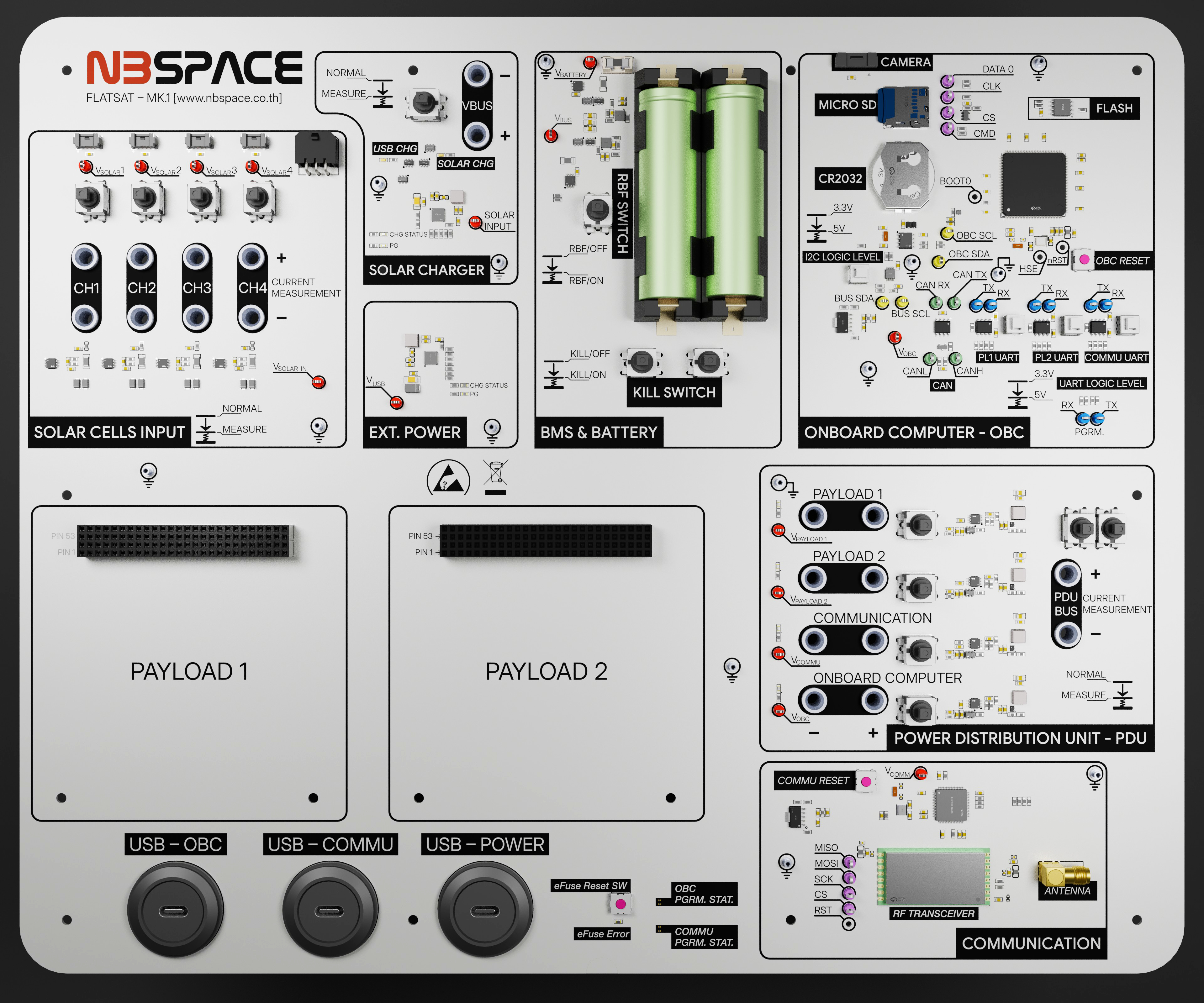
1. Probe Color Coding Standard
To keep the testing environment organized and prevent accidental misconnections, the FlatSat uses a standardized color-coding system for hook probes. When measuring signals on the board's test points, please adhere to these colors:
- 🟡 Yellow Probe: I2C signals (e.g., SDA, SCL)
- 🟢 Green Probe: CAN bus signals (e.g., CAN+, CAN-)
- 🔵 Blue Probe: UART signals (e.g., TX, RX)
- 🟣 Purple Probe: SPI signals (e.g., MISO, MOSI, SCK, CS)
- 🔴 Red Probe: Any Power line (e.g., 3V3_OBC, VBUS)
- 🔌 Banana Plugs: Used strictly to measure inline current flow.
2. Voltage and Signal Measurement (Hook Probes)
To measure the voltage of a power rail or to inspect a data signal using an oscilloscope or multimeter:
- Establish Reference Ground: First, connect the ground reference of your measurement tool. There are multiple dedicated Ground (GND) probes distributed across the board (e.g., H1-H10 test points). Always use the GND point closest to your measurement target to minimize electrical noise.
- Attach the Hook Probe: Attach the appropriately colored hook probe to the target Test Point (TP) or signal hook on the board.
- Note: Simply use a multimeter with reference to the ground probe to measure DC voltages.
- VBUS Terminology: On this board (as seen in the schematic), the term
VBUSrefers to the protected battery voltage. It is the main power rail that exists after the battery protection circuitry and before any local regulators or power distribution switches.
3. Current Measurement (Current Probes)
As illustrated in the schematic and EPS documentation, you can measure the current consumption of individual subsystems (OBC, COMM, Payload) or the current generated by the solar panels using the onboard slide switches and measurement headers.
How to use the Current Probes:
The slide switches on the board (e.g., SW20-SW23 for Solar Inputs, SW24-SW27 and SW29 for Power Outputs) operate in tandem with banana jacks/measurement headers.
- Direct Connection Mode (Switch ON): The switch is closed. Current flows directly through the PCB trace. The measurement terminals are bypassed.
- Measurement Mode (Switch OFF/Measure): The direct trace is broken. The current is forced to route through the external measurement terminals.
To measure current:
- Switch the target subsystem's slide switch to the measurement position.
- Connect a multimeter set to Ampere (A) mode using banana cables across the measurement headers.
- The multimeter now acts as a bridge, allowing you to measure the exact current flow inline.